Raspberry Pi read only SD card

This will be my first post about a project with the Raspberry PI. I wanted to build an internet radio but I was afraid to corrupt the file system on the SD card when I just power off the radio without shutting it down correctly. Also it is necessary to avoid extensive writing to SD cards because flash cells do not like too many writes. After that procedure you will not be able to permanently write to the SD card anymore. All writes will end up in the RAM and will be lost after reboot. If your project needs to write to files you will have to add another data partition to your SD card or you have to add an USB stick. Also do not do things like extensive logging, because this will fill up your RAM! It’s also worth spending a little bit more money for the SD card. Cards like a SanDisk Ultra or even SanDisk Extreme will speed up things quite a bit and they are also more reliable than no name SD cards. For most projects 8GB are also more than enough.

I found some hints on the internet but non of them really worked with the newest Debian “jessie” based image. So I spend  a weekend to get it to work – and to make sure I can find it again I write the steps down here.

Before you start this procedure I would recommend that you start with a small image “RASPBIAN JESSIE LITE” from the rasbian download page. Then add all packages which are needed for your project. This will make sure that your image stays small and that the boot time is not longer than necessary. During development at least I do try this and that until everything is working. This will leave a lot of “garbage” in your system. That’s why I always would start with a new “clean” image after development is finished. There you only add what is really needed. So now lets assume you have a system which is working fine and you want to write protect your SD card now.

Lets make sure Debian is up to date:

apt-get update
apt-get upgrade

Now we want to update the kernel and the firmware:

apt-get install rpi-update
rpi-update
reboot

Now we want to get rid of some things we no most probably will not need in our “embedded system”:

apt-get remove --purge triggerhappy cron anacron logrotate

We dont’t need normal rsyslog on most appliances – that’s why we replace it with the busybox.

apt-get install busybox-syslogd
dpkg --purge rsyslog

We also want to avoid swapping so we disable it:

dphys-swapfile swapoff
dphys-swapfile uninstall
update-rc.d dphys-swapfile remove

To speed up booting we disable some things:

systemctl disable bootlogs.service
systemctl disable console-setup.service
systemctl disable exim.service

On an appliance we want to make sure that it always runs. If something goes wrong we do not want it to get stuck. We better restart the system.

First we set some kernel parameters which will do the following:

  • vm.panic_on_oom = 1 -> will create a kernel panic if system is out of memory
  • kernel.panic = 10 -> will automatically reboot the system after 10 seconds in case of kernel panic

so we add the following lines to /etc/sysctl.conf

echo "# panic kernel on OOM" >> /etc/sysctl.conf
echo "vm.panic_on_oom=1" >> /etc/sysctl.conf
echo "# reboot after 10 sec on panic" >> /etc/sysctl.conf
echo "kernel.panic=10" >> /etc/sysctl.conf

The Broadcom SOC in the raspi does have also a hardware watchdog which we can enable. This will make sure that the system restarts if it becomes unresponsive in any way. To do that we have to do the following:

First we make sure the kernel module for the watchdog gets loaded at boot time. Therefore we add the following line to /etc/modules

echo bcm2708_wdog >> /etc/modules

Now we install the watchdog package:

apt-get install watchdog

Before we can start the watchdog we have to uncomment 2 lines:

  • max-load-1 = 24  # that tells the watchdog to  reboot when the load average 1min is higher than 24 may be on your system it has to be set higher or lower
  • watchdog-device = /dev/watchdog # because we do have the hardware watchdog
perl -p -i -e 's/#max-load-1/max-load-1/' /etc/watchdog.conf
perl -p -i -e 's/#watchdog-device/watchdog-device/' /etc/watchdog.conf

After that is done theoretically could start the service. But I found a bug in the unit file. To fix that we have to add WantedBy=multi-user.target to the [Install] section of /lib/systemd/system/watchdog.service

perl -p -i -e 's/\[Install\]/[Install\]\nWantedBy=multi-user\.target/' /lib/systemd/system/watchdog.service

Now we can enable and start watchdog

modprobe bcm2708_wdog
systemctl enable watchdog.service
systemctl start watchdog.service

Now it’s time to reboot.

Up to now you should be sure that everything really works as expected because we now will make the file system on the SD card read only.
amp;

first we have to install UnionFS which is an overlaying filesystem (you can mount from several different locations into the same folder). In case of collisions, UnionFS uses priorities for the filesystems. It is frequently used to create RAM-Disk Overlays for read-only systems, for instance also with Live CDs.

apt-get install unionfs-fuse

In the next step we will create a mount script in //usr/local/bin/mount_unionfs …

#!/bin/sh
 DIR=$1
 ROOT_MOUNT=$(awk '$2=="/" {print substr($4,1,2)}' < /etc/fstab)
 if [ $ROOT_MOUNT = "rw" ]
 then
   /bin/mount --bind ${DIR}_org ${DIR}
 else
   /bin/mount -t tmpfs ramdisk ${DIR}_rw
   /usr/bin/unionfs-fuse -o cow,allow_other,suid,dev,nonempty ${DIR}_rw=RW:${DIR}_org=RO ${DIR}
 fi

… and make it executable.

chmod +x /usr/local/bin/mount_unionfs

In the next Step we prepare some directories.

cp -al /etc /etc_org
mv /var /var_org
mkdir /etc_rw
mkdir /var /var_rw

Just to be sure we save the old fstab:

cp /etc/fstab /etc/fstab_rw

Now we modify the /etc/fstab to the following contents:

proc            /proc           proc    defaults          0       0
/dev/mmcblk0p1  /boot           vfat    ro                0       2
/dev/mmcblk0p2  /               ext4    ro,noatime        0       1
mount_unionfs   /etc            fuse    defaults          0       0
mount_unionfs   /var            fuse    defaults          0       0
none            /tmp            tmpfs   defaults          0       0

We copy that as well:

cp /etc/fstab /etc/fstab_ro

And now its time to reboot again.

If everything has worked the output of the command mount should look like this:

/dev/mmcblk0p2 on / type ext4 (ro,noatime,data=ordered)
devtmpfs on /dev type devtmpfs (rw,relatime,size=469760k,nr_inodes=117440,mode=755)
sysfs on /sys type sysfs (rw,nosuid,nodev,noexec,relatime)
proc on /proc type proc (rw,relatime)
tmpfs on /dev/shm type tmpfs (rw,nosuid,nodev)
devpts on /dev/pts type devpts (rw,nosuid,noexec,relatime,gid=5,mode=620,ptmxmode=000)
tmpfs on /run type tmpfs (rw,nosuid,nodev,mode=755)
tmpfs on /run/lock type tmpfs (rw,nosuid,nodev,noexec,relatime,size=5120k)
tmpfs on /sys/fs/cgroup type tmpfs (ro,nosuid,nodev,noexec,mode=755)
cgroup on /sys/fs/cgroup/systemd type cgroup (rw,nosuid,nodev,noexec,relatime,xattr,release_agent=/lib/systemd/systemd-cgroups-agent,name=systemd)
cgroup on /sys/fs/cgroup/cpuset type cgroup (rw,nosuid,nodev,noexec,relatime,cpuset)
cgroup on /sys/fs/cgroup/cpu,cpuacct type cgroup (rw,nosuid,nodev,noexec,relatime,cpu,cpuacct)
cgroup on /sys/fs/cgroup/blkio type cgroup (rw,nosuid,nodev,noexec,relatime,blkio)
cgroup on /sys/fs/cgroup/devices type cgroup (rw,nosuid,nodev,noexec,relatime,devices)
cgroup on /sys/fs/cgroup/freezer type cgroup (rw,nosuid,nodev,noexec,relatime,freezer)
cgroup on /sys/fs/cgroup/net_cls type cgroup (rw,nosuid,nodev,noexec,relatime,net_cls)
systemd-1 on /proc/sys/fs/binfmt_misc type autofs (rw,relatime,fd=22,pgrp=1,timeout=300,minproto=5,maxproto=5,direct)
debugfs on /sys/kernel/debug type debugfs (rw,relatime)
mqueue on /dev/mqueue type mqueue (rw,relatime)
configfs on /sys/kernel/config type configfs (rw,relatime)
fusectl on /sys/fs/fuse/connections type fusectl (rw,relatime)
none on /tmp type tmpfs (rw,relatime)
/dev/mmcblk0p1 on /boot type vfat (ro,relatime,fmask=0022,dmask=0022,codepage=437,iocharset=ascii,shortname=mixed,errors=remount-ro)
ramdisk on /var_rw type tmpfs (rw,relatime)
ramdisk on /etc_rw type tmpfs (rw,relatime)
unionfs-fuse on /var type fuse.unionfs-fuse (rw,relatime,user_id=0,group_id=0,default_permissions,allow_other)
unionfs-fuse on /etc type fuse.unionfs-fuse (rw,relatime,user_id=0,group_id=0,default_permissions,allow_other)

That’s it 🙂

If you want to do changes now put the SD Card into another computer and copy the fstab_rw over the changed fstab file and boot again in the rspi.

Flashing ESP Modules with Arduino IDE

If you want to flash new firmware onto your ESP8266 module GPIO 0 has to be connected to GND during powering up the module. Normally you would do that with a jumper wire or a little switch. Of course it would be good if it could be so comfortable like with an Arduino where you just press the upload button in the IDE and the controller is flashed.

But luckily this is possible as well with the ESP. Therefore 2 additional signals from the FTDI USB Serial adapter are used – RTS and DTR. On The github project page there is a schematics how the ESP module has to be connected to the USB serial adapter. I found out that the nodemcu-devkit modules already work out of the box. They can be purchased for less then 10€ on ebay.For other modules like the ESP01 module you can build your own adapter.

ESP_to_serial

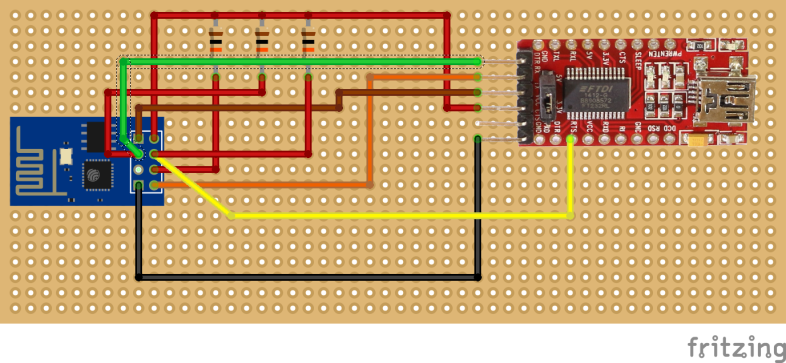
The schematics is mentioning a separate 3.3v power supply. I noticed that at least the FTDI USB serial converter I am using is capable to supply enough power to flash and test a ESP01 module. Since GPIO15 is not exposed on an ESP01 module I have only connected the upper 3 10k resistors. 2 of them (REST and CH_PD) I have soldered directly to the module because they are more or less always needed. the one going from 3V3 to GPIO0 is in the adapter cable. The wiring is like this:

esp01-ftdi_bb

Make sure you set the voltage jumper to 3.3V !!!

ESP8266 with Arduino IDE

It has been a while since I had time to write something here. But there is one thing which I found last week, which should be mentioned here. There is a great project on github which adds support for the ESP8266 to the standard Arduino IDE. This is good news because there are so many examples and projects for Arduino boards on the net which now can be used with the ESP8266 as well. Basically the ESP is now like any other Arduino board. To get this working you have to install the Arduino IDE on your computer. It will work on Linux OSX and Windows. In order to work with the ESP you will have to use the 1.6.x version. You can get it from the Arduino download page. I have tested it with the 1.6.5 version under OSX and Windows. Installing support for new boards is very easy.

  • Open in the menu the Preferences and past the following URL at the field “Additional Boards Manager URLs:”
    http://arduino.esp8266.com/stable/package_esp8266com_index.json
    esp-arduino-1
  • Press OK
  • Open Tools -> Board -> Boards Manager
  • At the Type drop down select Contributed
  • Now you should see a section for the esp8266 – klick on it and press Install. This will download everything you need and you are done with the installation

If the steps above have worked you can now select several ESP8266 based boards. If you do not have any of the mentioned boards you can always select Generic ESP8266 board.

There are also some examples which can be found on the github page as well. General information can be found on the homepage of the project.

ESP8266 as a WEB server

Since the ESP firmware has a complete IP stack it can also act as a server in an IP network. Of course you will not be able to run a full featured WEB server on such a device. But that is also not necessary to do some useful tasks.

If you want to do some home automation – web services are a simple way to connect things together. In my example I have a little web server which controls a GPIO pin of the ESP. You can turn it on an off and ask for the current state. To add some security also have to submit a PIN as well. If you want to make sure that your home automation is save you should run all components in a separate WLAN. The script will do the following.

If you do not use the right pin the TCP connection is closed without any response. This example can easily extended to control more pins or display values from sensors.

-- script will start a http server on http_port
-- requests do look like
-- http://espmodule.domain/?PIN=1234&switch=ON
-- PIN is just a little bit of security to avoide someone playing around
-- switch=ON will turn switch_pin to high
-- switch=OFF will turn switch_pin to low
-- switch=status will just print ON or OFF

switch_pin   = 0         -- ESP pin to be controlled
switch_state = "OFF"     -- initial state
PIN          = "1234"    -- pin code 
http_port    = 80        -- port of http server
module_name  = "kitchen" -- just give the module a name

gpio.mode(switch_pin, gpio.OUTPUT)
gpio.write(switch_pin, gpio.LOW)

-- deliver static content (just to make the code more readable)
function page(what)
 local content = ""
 if what == "start" then --httppage header
  content = content .. "<!DOCTYPE HTML PUBLIC \"-//W3C//DTD HTML 4.01 Transitional//EN\"\n"
  content = content .. "\"http://www.w3.org/TR/html4/loose.dtd\">\n"
  content = content .. "<html>\n<head>\n<title>NODE MCU TEST</title>\n</head>\n<body>\n"
  content = content .. "<h1>ESP8266 module "..module_name.."</h1>\n"
  end
 if what == "end" then --close http page
  content = content .. "</body>\n</html>"
 end
 return content
end

--define what is happening if server is contacted
server = net.createServer(net.TCP) 
server:listen(http_port,function(conn) 
 conn:on("receive", function(client,request)
  -- this code block gets the params of the http request und stores that in params
  local _, _, method, path, vars = string.find(request, "([A-Z]+) (.+)?(.+) HTTP");
  if(method == nil)then 
   _, _, method, path = string.find(request, "([A-Z]+) (.+) HTTP"); 
  end
  local params = {}
  if (vars ~= nil)then 
   for param, value in string.gmatch(vars, "(%w+)=(%w+)&*") do 
    params[param] = value
   end 
  end
  -- now the code which is doing something based on the request
  if params.pin == PIN then
   local message = ""
    if(params.switch == "ON")then
     message = "<h1>Turning switch ON</h2>\n";
     gpio.write(switch_pin, gpio.HIGH);
     switch_state = "ON"
    elseif(params.switch == "OFF")then
     message = "<h1>Turning switch OFF</h2>\n";
     gpio.write(switch_pin, gpio.LOW);
     switch_state = "OFF"
    elseif(params.switch == "STATE")then
     message = "<h1>state: "..switch_state.."</h2>\n";
    end
    client:send(page("start")..message..page("end"));
   end
  client:close();
  collectgarbage();
 end)
end)

You can test with a normal web browser or on the command line. For instace with wget or curl.
It will look like this:

curl "http://espmodul.home/?pin=1234&switch=ON"

the response will be

ESP8266 module kitchen
Turning switch ON

Reading temperature and humidity from a DHT22 sensor

One use case for a ESP8266 module is measuring temperature and humidity. On very common sensor is the DHT22. You can get if for about 4-5$ at eBay. Because it has only one data pin an ESP-01 module would be good enough. The DHT22 is also supported out of the box the module you need can be found in the nodemcu firmware under lua-modules/dht22/dht22.lua.

The example below will only work with the floating point version of the nodemcu software correctly. The integer version will only show the integer part of the values.

-- This script will read temperature and humidity from a DHT22 sensor
-- Use the floating point version of the nodemcu firmware
PIN = 2 -- data pin of DHT22
dht22 = require("dht22") --can be found in nodemcu from GitHub under lua-modules/dht22/dht22.lua
dht22.read(PIN)
temperature = dht22.getTemperature()/10 -- DHT22 module returns integer of 0.1 deg C
humidity = dht22.getHumidity()/10 -- DHT22 module returns integer of 0.1 %
if humidity == nil then
 print("Error reading from DHT22")
else
 -- temperature in degrees Celsius
 print("Temperature: "..temperature.." deg C")
 -- humidity
 print("Humidity: "..humidity.."%")
end
-- release module
dht22 = nil
package.loaded["dht22"]=nil

dht22

Just connect pin 1 to 3.3V, pin 2 to the ESP data pin and pin 4 to GND. Pin 3 is unused.

init.lua

After you have successfully flashed the nodemcu firmware and your IDE is running. It is important to tell the ESP module what to do after power on.

The nodemcu firmware is trying to execute a file called init.lua. You can of course name your script always init.lua but then you are limited to one filename, which might be confusing :-).

One thing which always need to be done is the configuration of the WIFI networking. That’s why I have created an init.lua file which does that and executes another LUA script after that is done. You can choose to put your module in station mode (when it’s suposed to be part of an existing WLAN) or the module can be an access point (then it creates it’s own WLAN.

-- This script is automaticaly executed during startup of the module
-- It will either configure the module to be an Access Point or a Station in an existing WLAN and start another LUA scrip

mode = "ap" -- define the WIFI mode Station or Access Point
startup = "test.lua" -- which main script gets executed after network config is done
SID = "test" -- define SID
password = "12345678" -- define the password

print("starting in "..mode.." mode")

-- configute the module to ba an access point with SID and password
-- after that start the script defined in startup
if mode == "ap" then
 wifi.setmode(wifi.SOFTAP);
 wifi.ap.config({ssid=SID,pwd=password});
 print("ESP8266 mode is: " .. wifi.getmode())
 print("The module MAC address is: " .. wifi.ap.getmac())
 print("Config done, IP is "..wifi.ap.getip())
 dofile(startup)
end

-- configure the module to join the existing network with SID and password
-- It will wait until the module gets an IP from the router with DHCP
-- after that start the script defined in startup
if mode == "station" then
 wifi.setmode(wifi.STATION);
 wifi.sta.config(SID,password)
 wifi.sta.connect()
 tmr.alarm(1, 1000, 1, function()
  if wifi.sta.getip()== nil then
   print("IP unavaiable, Waiting...")
  else
   tmr.stop(1)
   print("ESP8266 mode is: " .. wifi.getmode())
   print("The module MAC address is: " .. wifi.sta.getmac())
   print("Config done, IP is "..wifi.sta.getip())
   dofile(startup)
  end
 end)
end

Writing LUA code fore ESP8266 nodemcu firmware

Things you need

  • First you need to install nodemcu firmware on the ESP module – please see my other posts how to do that.
  • Connect your ESP to your PC using a USB/serial converter with 3.3V signal level (see my other post).
  • Power the ESP module with 3.3V – never 5V.
  • There is a JAVA based IDE for the ESP8266. It’s called ESPlorer.
    ESPlorer-screen
    You can get the tool here. It allows you to edit your scripts with syntax highlighting, upload and execute them, execute single commands and many other useful things. If you should have problems when uploading your scripts you can disable the “Turbo mode” in the settings TAB. For me that helped a lot. I have tested the ESPLorer on OSX, Windows and Debian Linux. You need a JAVA 7 runtime to start it.

Things you should read

There are man examples and projects on the internet. If you have time, you can get some inspiration for your own projects. The best place to start ist the nodemcu API reference page.

Flashing new firmware onto ESP8266

When you get your ESP module it has most likely the default AT firmware installed and even this is not up to date. That’s why the first Thing you want to do is upgrading firmware.

There is the the so called AT firmware, which is the default one. This can be used fore instance together with an Arduino. The best source I fount for this firmware is linked on this page.

If you want to write your own code in LUA you should use the modified software which comes from the open source project nodemcu.

If you want you can cross compile your own firmware out of the source. So fare I have not taken the time to do this. It is also possible to download pre built firmware images which are not too far behind the latest source code. The download page is here. There are 2 versions one is the integer version the other one is the floating point version. I am always using the floating point version. It is slightly bigger but better if you need to deal with floating point values.

To flash the firmware you can use a python based esptool tool which I have tested on OSX and linux. If it works on Windows as well I cannot tell. For windows there is also a special tool – nodemcu-flasher – but I have never used it.

It is important that you need to connect GPIO 0 of the ESP-Module to GND before you power the module on. That will put the module in a special mode which allows you to flash the firmware. With esptool you would do the following:

  • get esptool.py
  • download firmware image (the *.bin file)
  • connect GPIO 0 to GND
  • toggle power
  • execute the following command:
/path-to-esptool/esptool.py -p /dev/serial-device write_flash 0x000000 /path-to-firmware/firmware-file.bin
  • wait until it’s finished
  • disconnect GPIO 0 from GND
  • toggle power

Now you can connect to the ESP chip using a serial terminal program (9600 8 N 1 – no local echo). Make sure that you configure the terminal to send CR and LF after pressing enter.

To test if LUA the firmware is active you can enter:

print("123") <ENTER>

It should print 123 😉

ESP8266 Development board

To get started with the ESP8266 I found a development board, which has already several components integrated. These are:

  • 1 Relais
  • 1 DHT11 temperature and humidity sensor
  • 2 switches
  • 1 potentiometer to generate different voltage at the ADC pin
  • 1 buzzer
  • 1 RGB LED

esp8266-devboard

On the board there is also a usb/serial converter to directly connect the board to the PC and a voltage regulator, which generates the 3.3V for the ESP chip. You can get it at eBay or Aliexpress starting 15$. It comes with the ESP module.

The unit consists of 2 boards. One is the ESP8266 module without all the peripherals and usb/serial chip. This board can be purchased also separately for about 4$.

esp8266-module

It is breadboard friendly and has an antenna connector. The second board does have all the other components. The different components on the board can be enabled separately using some DIP switches. All external pins of the ESP module are also accessible via pins on the board. So you cannot only work with the on board components.

The USB/serial converter on this board is a CH-341 chip. It did work out of the box on Debian Linux, but not on OSX and Windows. Drivers for thees operating systems can be downloaded here:

Unfortunately this development board comes without any documentation. I was also unable to find any on the internet. With try and error I was able to find out most of the things. The only thing I was not able to get working is the red LED. May bee there is something broken on my board. If you have something to add – please et me know.

Function nodemcu pin number ESP8266 GPIO DIP Switch number to enable
Relais 0 16 5
RGB LED green 7 13 2
RGB LED blue 6 12 3
Buzzer 1 5 5

Switches

  • Switch 1 ON/OFF switch
  • Switch 2 nodemcu 3
  • Switch 3 nodemcu 4

DIP switches

DIP Switch Function
1 ???
2 RGB LED Green
3 RGB LED blue
4 ???
5 Relais
6 Buzzer
7 has to be always one
8 turn on to flash firmware

On board DHT11 / DHT22

Pin2 in nodemcu firmware (GPIO 4)

ESP8266 Modules

There are various boards with the ESP8266 chip available. The best sources for the modules are eBay or Aliexpress. Mostly they will get shipped directly from China. If you cannot wait you can get the meanwhile also in Europe or the US bit the price will be significantly higher. The ESP-01 module is more suitable for a breadboard because of the 0.1 in pitch of the pins.  The other modules are mostly to be used on SMD boards. There are also adapter board available which do allow the usage of the other boards on a breadboard as well. This website has a good summary. The main difference between the modules is mostly which IO pins are available.

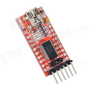
To configure the modules you have to use a serial / USB converter. They are sold very cheap on eBay. I would use one with the FT232RL chip. It will run on Windows, Linux and OSX. There are many different adapters. The one I am using looks like this:

ft232rl

It can also be adjusted to work with 3.3V signal level and can also supply the ESP module with 3.3V. To adjust this use the little jumper.

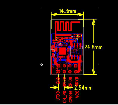
To connect this module with the ESP-01 board (at eBay less than 2€)

esp01-dim-b

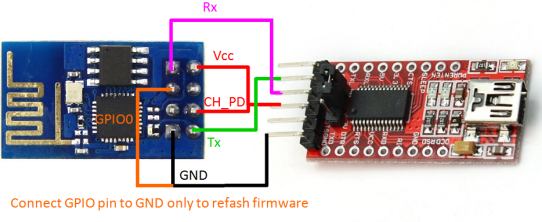
use the following picture:

esp-01-ft232

The CH_PD pin (chip power down) needs to be connected to VCC in order to use the module. GPIO0 needs to be connected to GND in order to flash new firmware onto the chip. After flashing it can still be used as GPIO.

The default firmware on these modules does only allow AT commands like on modems over the serial interface. There are some examples on the net, how you can use this default firmware together with Arduino boards. This is nice if you are looking for a inexpensive way to extend a Arduino based project with a WIFI module. Pay attention to the signal level ! Most Arduinos do use 5V – this will kill the ESP8266.

But if you do not depend on Arduino it is probably better to use the ESP module direct, because there is a project called nodemcu firmware. This is an extension of the default firmware with a built in LUA interpreter. The way this works is very similar to node js (event loop) but with LUA syntax. For those who have not worked with LUA before – it is very similar to C but you don’t have to declare variables. This is under very active development and gets support for more and more sensors and even little OLED displays.